
How LEGO Technic Works and What Goes Wrong
Identify what connections should hold or move, keep mechanism supports rigid, treat gear calculations as idealized, and test modules before they are concealed.
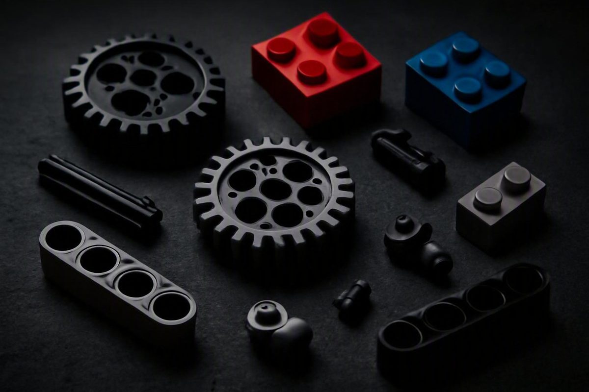
Build better moving models, from the first pin to the final function test.
LEGO Technic becomes easier to understand when you stop seeing a model as one long sequence of parts and start seeing it as a collection of structures and mechanisms. Every connection has a job: hold elements rigidly, create a pivot, support an axle, transmit rotation or keep moving parts aligned.
This guide covers the core parts, rigid construction, basic gear relationships, a progressive learning route, modular building, troubleshooting and the main types of instruction resources. The central method is simple: determine what should hold and what should move, build stable support around each mechanism, and test every accessible stage before concealing it.
How to Use This Guide
Choose the route that matches your goal:
- Learn the fundamentals: Start with the core-parts section, then continue through connections, structural reinforcement and gearing.
- Find instructions for a numbered set: Go to the resource section. LEGO’s official instruction service should be your first stop.
- Diagnose a malfunction: Begin with the modular-testing section, then follow the symptom-based troubleshooting sequence.
- Explore older sets and elements: Use the historical-resource guidance, noting the dates and limits of each archive.
Different resources serve different purposes. LEGO’s official building-instructions service is the authoritative starting point for a numbered set. LEGO Education provides focused mechanism exercises, often tied to particular educational kits. Technica is an unofficial historical archive. Community tutorials and MOC catalogues offer ideas and custom instructions, but they are not official LEGO guidance.
This article does not replace a set’s building manual, reproduce complete LEGO instructions or reproduce paid MOC instructions. When building a set, follow its specified parts and orientations. Use the principles here to understand why the mechanism works, test it methodically and locate mistakes.
Treat general connector rules as starting points, not universal laws. A low-friction connection may be appropriate at an intended pivot but unsuitable in a joint that must resist movement. A firm connector may stabilize a frame but obstruct a mechanism if substituted at an articulation point. Geometry, load, surrounding supports and the exact assembly all matter.
The question to ask throughout is not simply, “Is this connection strong?” It is:
“Is this connection doing the correct job—holding, pivoting, supporting or transmitting motion?”
The Core Technic Parts and What Each One Does
A useful Technic vocabulary begins with the jobs parts perform. You do not need to memorize every element number, axle length or connector angle before building. You do need to recognize the difference between a structural member, a connector and a rotational component.
Beams and liftarms
Beams and liftarms form the skeleton of many Technic assemblies. Their evenly spaced holes accept pins and axles, allowing structural members and mechanisms to use a consistent layout.
Straight elements are useful for rails, chassis sides, axle supports and parallel frames. Angled elements let a structure change direction, provide bracing or fit around mechanical components. The important distinction is functional: a beam generally carries and locates other parts, while an axle or gear carries motion.
A single beam can connect several points, but that does not automatically make the resulting assembly rigid. Rigidity depends on the complete shape, the way its joints are reinforced and the forces applied by the mechanism.
Pins
Pins commonly connect beams, liftarms, frames and connectors. Some pin connections are intended to hold structural parts firmly. Others are selected because a component must pivot with relatively little resistance.
Do not identify a pin only by its general appearance and assume it is interchangeable with another. In an official model, pin choice forms part of the mechanism’s design. Indiscriminate substitution can introduce unwanted looseness or resistance.
Axles
Axles support and transmit rotation. Gears, wheels and other rotating components can be mounted on an axle so that motion entering at one point reaches another.
An axle may also locate a component, but it should not automatically be treated as a substitute for a structural pin. If an axle must turn, every support along its path must allow the intended motion. An incorrectly oriented connector can lock an axle that was supposed to rotate.
Gears and frames
Gears transfer rotation between axles. Their relative sizes determine the idealized relationship between input and output motion, while their placement and support determine whether that relationship works smoothly in the model.
It does not correct every weak assembly, but it can provide a dependable foundation.
Technic and standard LEGO elements
Technic structures can be combined with conventional stud-based construction through suitable adapters, including bricks with holes and pin-based connections. This is also where SNOT, meaning “Studs Not on Top,” can be useful: standard elements can be oriented sideways or integrated around a Technic frame to create bodywork, surfaces and details.
Keep structural and decorative jobs separate in your mind. Bodywork may tie an assembly together, but do not assume that a decorative panel is responsible for maintaining gear alignment unless the model’s instructions make it part of the supporting structure.
| Element family | Primary job | Normal load role | First thing to inspect if used incorrectly |
|---|---|---|---|
| Beams and liftarms | Form the supporting structure | Primarily structural | Flex, open shapes and poorly supported joints |
| Pins | Connect or articulate elements | Structural or pivoting, depending on the assembly | Whether the joint should hold firmly or move |
| Axles | Carry rotation and mounted components | Primarily rotational | Whether the axle is straight, seated and free to turn |
| Gears | Transfer motion between axles | Rotational | Tooth mesh, spacing and axle alignment |
| Frames | Keep connection and axle locations aligned | Structural support around mechanisms | Distortion, incomplete attachment or trapped components |
| Technic-to-System adapters | Join stud-based and hole-based construction | Usually structural or bodywork integration | Orientation and interference with moving parts |
Original visual brief: Create simplified line diagrams of a beam, liftarm, pin, axle, gear and rectangular Technic frame. Add a separate cutaway showing a Technic beam connected to a brick with a hole and a sideways stud-based panel. Label each element by function, not part number. Use original artwork rather than copying LEGO instruction graphics.
Before progressing, practice sorting loose parts by job. Place structural members in one group, pins and connectors in another, and rotational parts in a third. This simple distinction makes instruction steps easier to interpret and mechanical mistakes easier to recognize.
Connections and Rigid Structures: Hold Firm Where Nothing Should Move
A reliable Technic structure separates intentional movement from accidental movement.
As a general rule, firmer friction connections suit joints that should remain stable, while lower-friction connections may suit pivots or articulations that need to move. Triangulation, reinforced joints and additional beams or liftarms are also commonly suggested as ways to reduce flex in beginner Technic construction (see the third-party overview of these techniques). These are general principles, not permission to substitute connector types in an official set.
A pivot should move locally
Suppose a suspension arm pivots around one connection. The arm should rotate at that axis, but the frame holding the pivot should remain stable. If both the arm and its support twist, part of the input is being absorbed by structural movement.
That distinction helps identify the real problem:
- Intended articulation: Motion occurs at a defined axis and follows a repeatable path.
- Unwanted looseness: Adjacent supports shift, separate or twist.
- Binding: The designated pivot resists motion because parts are misaligned, overconstrained or rubbing.
Do not assume that adding connectors everywhere will improve the model. Extra bracing can trap an axle, distort parallel members or prevent an articulated component from completing its intended travel.
Close and brace structural shapes
An open chain of beams can fold or twist at its joints. Where the design permits, connect members into closed shapes. Parallel members joined at several points can support one another, while diagonal reinforcement can resist deformation that an open corner does not.
Triangulation is useful because a diagonal member helps prevent a rectangular arrangement from changing shape. Reinforcing a joint from more than one direction can also reduce twisting. Additional beams or liftarms can distribute support across a wider part of the model.
Every reinforcement must respect the mechanism inside the structure. A brace that stiffens the chassis but rubs against a rotating gear has not improved the complete assembly.
Keep axle supports aligned
Gear axles need to remain correctly positioned relative to one another.
When reinforcing a gearbox or axle housing:
- Identify each point supporting the relevant axles.
- Check whether members intended to be parallel remain parallel.
- Close open structural shapes where the design permits.
- Brace joints exposed to twisting.
- Confirm that added members do not touch gears, linkages or suspension components.
- Turn each installed axle slowly after every change.
That final test matters. A frame can feel stronger in your hands while making its mechanism less effective. Rigidity is useful only when it preserves the intended geometry and movement.
Rigidity checklist
- Are opposite or parallel structural members correctly aligned?
- Is an open corner flexing when the mechanism is loaded?
- Can the shape be closed or diagonally braced without obstructing motion?
- Are axle supports attached on both sides where the design calls for it?
- Does a designated pivot move while its surrounding mount stays stable?
- Are joints exposed to twisting reinforced in more than one direction?
- After reinforcement, do the affected axles still rotate freely?
- Do steering and suspension still complete their intended travel?
Original visual brief: Show two simplified versions of the same joint. The “before” version should be an open, unbraced corner visibly skewing under a curved force arrow. The “after” version should add diagonal or parallel reinforcement while leaving a nearby axle clear. Label “unwanted frame movement” and “designated moving axis.”
Gears Without Guesswork: Speed, Torque and Smooth Meshing
For the examples in this section, the driving gear is the input and the driven gear is the output.
The basic relationship is:
- A larger driver turning a smaller driven gear increases idealized output speed and reduces idealized output torque.
- A smaller driver turning a larger driven gear reduces idealized output speed and increases idealized output torque.
This is a tradeoff, not a way to obtain more speed and more torque simultaneously.
Example: 24-tooth driver and 8-tooth driven gear
Divide the number of teeth on the driver by the number on the driven gear:
24 ÷ 8 = 3
1 input rotation → 3 output rotations
This example applies the supported general relationship between gear size, speed and torque; it remains an idealized calculation rather than a measured physical result.
Example: 8-tooth driver and 24-tooth driven gear
Reverse the roles:
8 ÷ 24 = 1/3
3 input rotations → 1 output rotation
The calculation describes what the gear pair is trying to do; it does not promise exact physical speed or torque.
Decide which tradeoff the mechanism needs
Use a reduction when the output needs more turning effort and can move more slowly. Use a speed increase when a lightly loaded output needs to rotate faster. Then test the complete motion path rather than judging the mechanism only by the two visible gears.
The downstream mechanism can expose weak axle support or marginal gear mesh.
Smooth meshing depends on structure
Two correctly selected gears can still perform poorly if their axles are not positioned and supported correctly. Symptoms can include:
- repeated tooth clicking;
- one gear climbing over another;
- smooth rotation through part of a cycle but resistance elsewhere;
- gears separating when load is applied;
- an axle shifting lengthwise;
- the surrounding frame spreading or twisting.
Slow hand rotation makes it easier to observe where resistance begins. Use this inspection sequence:
- Disconnect or unload the output if the design makes that practical.
- Turn the input slowly by hand.
- Watch the first gear pair through a complete rotation.
- Continue along the motion path one pair at a time.
- Check that each axle remains aligned and supported.
- Inspect component spacing and nearby parts that could rub.
- Look for resistance farther downstream.
- If teeth repeatedly click, skip or climb, pause and inspect the motion path before continuing the test.
Axial position matters
A gear may be mounted on the correct axle yet sit in the wrong position along it.
Compare spacing and orientation with the applicable instructions. Check that bushes, connectors and neighboring gears sit where the relevant step specifies. Do not treat all side-to-side clearance as an error; a moving assembly may need some clearance to operate.
Worm gears: useful but conditional
The cited beginner overview characterizes worm gears as useful for substantial speed reduction and increased torque, and says they can resist backward motion. Treat that last behavior as configuration- and load-dependent rather than guaranteed. The supplied evidence does not establish that every worm arrangement is non-back-drivable.
For an early experiment, a pair of ordinary gears is easier to observe and diagnose. Add specialized arrangements after you can distinguish a ratio problem from an alignment or support problem.
A practical bench test
Build a small rigid frame containing one 8-tooth gear and one 24-tooth gear. Mark the input and output axles with removable pointers.
Test both arrangements:
- Turn the 24-tooth gear once and count the output rotations.
- Reverse the roles and turn the 8-tooth gear three times.
- Apply light finger resistance to the output and observe where the structure flexes.
- Compare the mechanism with one axle support temporarily made less rigid.
- Restore the intended support before installing the mechanism elsewhere.
The goal is not merely to confirm the arithmetic. It is to connect the ratio, physical resistance and quality of the supporting structure.
A Progressive Route From Simple Mechanisms to Working Vehicles
There is no single required Technic curriculum. A useful progression moves from mechanisms that expose one principle to models in which several principles interact:
- rigid structure;
- lever and wheel-and-axle models;
- pulleys and gears;
- cams, pawls and ratchets;
- steering and suspension modules;
- drivetrains and differentials;
- pneumatics;
- motorized mechanisms.
LEGO Education provides downloadable exercises covering levers, wheels and axles, pulleys, inclined planes, gears, cams, pawls, ratchets and structures. Its resources also progress to complete models such as a sweeper, windmill, clock and gear racer, plus pneumatic builds including a scissor lift, robot hand, stamping press and robot arm. The filenames associate groups of these resources with Education sets 9686, 9641 and 9689, so builders may not possess the required inventory (browse the LEGO Education Machine & Mechanism resources).
These files are mechanically relevant, but they are not ordinary retail Technic-set manuals.
| Stage | Mechanism | Practice objective | Suggested resource type | Test before moving on |
|---|---|---|---|---|
| 1 | Rigid frame | Hold axle locations without twisting | Simple self-built exercise | Push diagonally and check for unwanted deformation |
| 2 | Lever; wheel and axle | Identify input, pivot and output | LEGO Education principle model | Move through the complete range without rubbing |
| 3 | Pulley or simple gears | Observe direction and ratio | Focused mechanism exercise | Count input and output rotations |
| 4 | Cam or ratchet | Convert or control motion | Education exercise or reviewed tutorial | Complete several cycles without jamming |
| 5 | Steering and suspension | Combine pivots with rigid supports | Visible module or community tutorial | Check steering travel and suspension return where designed |
| 6 | Drivetrain and differential | Distribute rotation through several components | Set module or custom chassis lesson | Turn the input and observe all expected outputs |
| 7 | Pneumatics | Control remote linear movement | Kit-specific Education instructions | Test the complete action before installation |
| 8 | Motorized mechanism | Integrate powered input with an existing mechanism | Model-specific instructions | Confirm unobstructed hand movement before following the power instructions |
A community-produced tutorial index includes examples involving steering, suspension, drivetrains, pneumatics, winches, clutches, motorized mechanisms and custom vehicle chassis (view the indexed Technic tutorials). Treat these as creator demonstrations rather than official specifications, and do not rely on promotional labels such as “simplest,” “most compact” or “powerful.”
This guide does not establish compatibility or operating precautions for motors, hubs, batteries, sensors or pneumatic components. Use the model- or kit-specific instructions and compatibility information before powering or pressurizing an assembly.
Choose a project by what it teaches
Piece count alone does not explain what a project will teach. A small mechanism may be difficult to inspect if its axles are densely packed or its timing is sensitive. A larger model may be easier to understand if its functions remain visible and its modules can be tested separately.
Choose your next project by asking:
- What mechanism do I want to understand?
- Can I see the input, transfer path and output?
- Can I test the module before it is installed?
- Do I have the required parts?
- Are the instructions complete and legible?
- If something binds, can I reach the likely cause?
- Does the project introduce one major new idea or several at once?
A visible steering module may teach more than a vehicle whose steering is immediately buried. An open-frame differential is easier to study than one installed deep inside a complete gearbox.
Progress when you can explain what each connection does and predict the output before turning the input. That understanding transfers to unfamiliar sets and custom models more effectively than memorizing one build sequence.
Build in Modules and Test Before the Mechanism Disappears
Complex Technic models become more manageable when divided into subassemblies. A module might be a front axle, rear suspension, gearbox, steering unit, lifting arm or body section. Build and test each one before final integration.
This is both a building method and a diagnostic method.
Organize work by instruction stage
For a numbered set, keep the parts for the current stage together. Before closing a gearbox or frame:
- confirm that visually similar gears are the specified gears;
- compare connector and cross-block orientation with the image;
- verify axle insertion depth;
- check left-right and front-rear orientation;
- make sure joints that should align are aligned;
- rotate the accessible mechanism slowly.
This is practical workflow advice, not an additional official LEGO requirement. The set instructions remain authoritative.
Use milestone tests
Structure
- Hold the module at its intended mounting points.
- Apply light pressure in the directions in which the mechanism will load it.
- Look for joints that shift independently of the rest of the frame.
- Verify that reinforcement has not trapped an axle.
Steering
- Move from center toward both limits.
- Confirm that links remain connected and clear of nearby parts.
- Check whether the intended hubs respond together.
- Compare the travel with the applicable instructions.
Suspension
- Press each side through its designed travel.
- Watch the pivot points rather than only the wheel.
- Confirm appropriate return where the design provides it.
- Check connector orientation and spring attachment.
Drivetrain or gearbox
- Rotate the input slowly by hand.
- Observe whether motion reaches the expected output.
- Test relevant selections or positions before enclosure.
- Investigate repeated clicking or abrupt resistance while the assembly remains accessible.
Photograph major milestones
A clear photograph taken before a gearbox is closed can later answer several questions: Which gear was installed? Which way did a differential face? Was an axle fully seated? Which connector orientation is now hidden?
Photograph both sides and any dense internal layer. If a problem appears later, compare the motion path with these images and identify the shortest access route.
A detailed third-party guide to Technic set 42110 documents how an incorrect gear, reversed differential, wrongly oriented cross block, partially inserted axle or misaligned universal joints can disrupt later operation (review the Defender-specific checkpoints). These are set-specific inspection lessons, not claims that every copy or every Technic model has those defects.
Printable pre-enclosure checklist
- [ ] Every gear and connector matches the current instruction stage.
- [ ] Directional and angled parts have the specified orientation.
- [ ] Axles are inserted to the specified depth and seated where required.
- [ ] Universal joints and linked shafts are aligned as shown.
- [ ] The input rotates smoothly by hand.
- [ ] Motion reaches the expected output.
- [ ] The output moves in the expected direction.
- [ ] The supporting frame remains stable.
- [ ] Pivots and suspension components complete their intended travel.
- [ ] No part rubs unexpectedly against a gear, axle or linkage.
- [ ] Any unexplained element from the current stage has prompted a review.
- [ ] Milestone photographs have been taken before enclosure.
A leftover element does not identify where an error occurred. Treat it as a prompt to review the current stage rather than as proof of a particular mistake.
Troubleshooting Binding, Clicking and Reversed Motion
Start with the symptom and trace the motion path instead of dismantling the model randomly.
For a vehicle drivetrain, a useful path is:
wheels or manual input
→ differential
→ universal joints or connecting shafts
→ gears or gearbox
→ output axle
→ moving engine or driven tool
The exact sequence varies by model. The diagnostic principle does not: establish the last point that works and the first point that does not.
Isolate the fault boundary
Turn the input slowly while watching the mechanism. Ask:
- Does the input move?
- Does the first connected axle move?
- Does motion cross the next gear pair or joint?
- Do both sides of a differential behave plausibly?
- Does resistance remain when an accessible downstream load is disconnected?
- Is the frame flexing where motion stops?
A component near the sound is not necessarily the cause.
If the drivetrain will not turn
Possible inspection points include:
- an incorrect gear;
- a missing gear;
- an axle passing through an opening that prevents the required rotation;
- a differential installed in the wrong orientation;
- a partially inserted axle;
- an obstructed gear or linkage;
- resistance in the engine, tool or other output.
Several of these checkpoints are documented in the set-specific Defender guide rather than established as universal Technic defects. Use them as hypotheses, then verify the applicable model against its own instructions.
A hobby account concerning Technic set 42009 describes a completed crane that failed because an internal gearbox gear had been omitted. The repair required substantial partial disassembly, illustrating the value of testing before enclosure (read the set-specific repair account). Its chassis-flexing repair method is an anecdotal response to one model and is not recommended here as a general procedure.
If the mechanism clicks or rotates unevenly
Inspect the system in this order:
- Gear mesh: Are the teeth engaged throughout a complete rotation?
- Axle alignment: Do the supports hold the axles in the intended positions?
- Universal joints: Are connected joints oriented as the instructions show?
- Spacing: Can a gear slide away from its partner or rub a neighbor?
- Frame rigidity: Do supports separate as resistance rises?
- Downstream load: Does the symptom change when an accessible later mechanism is disconnected or unloaded?
The aim is to locate the first point at which smooth motion becomes uneven, rather than trying to overcome the symptom with greater input force.
If front and rear sections fight each other
Inspect differential orientation. In the documented 42110 assembly, reversing one differential can make the front and rear drivetrains oppose one another instead of cooperating through the center mechanism.
Opposing wheel movement is not automatically a fault, however. With a differential, turning one wheel can cause another to rotate in the opposite direction during certain tests. That behavior alone does not prove incorrect assembly. Evaluate whether motion can travel through the intended drivetrain and compare differential orientation with the official instructions.
If suspension sits low or moves poorly
Check:
- spring attachment points;
- pin and connector orientation;
- left-right symmetry;
- whether an arm is reversed;
- whether bodywork or a drivetrain component blocks travel;
- whether the supporting frame is distorted.
In the 42110 guide, attaching the rear springs through the wrong holes is identified as a cause of impaired suspension and a low rear stance. That is an illustration of how one attachment position can matter, not a universal diagnosis for every suspension model.
Use minimal disassembly
Once you have identified a suspected component:
- Photograph the intact model and the area to be opened.
- Divide the exterior mentally into removable layers.
- Remove only enough material to expose the next checkpoint.
- Keep each layer grouped in removal order.
- Test as soon as the suspected component becomes accessible.
- Stop expanding the opening when the fault boundary is confirmed.
- Rebuild one layer at a time and repeat the function test.
If a proposed access method depends on heavily distorting the surrounding structure or pulling against a loaded assembly, choose a broader disassembly route instead. This is a conservative workflow recommendation, not a claim that a particular removal method is safe for every model.
| Symptom | First checks | What the result suggests |
|---|---|---|
| Rotation completely blocked | Gear selection, axle path, differential orientation, downstream mechanism | Find the first stationary component after a moving input |
| Repeated clicking | Gear mesh, axle support, frame flex, spacing, downstream load | Teeth may be separating or climbing as resistance rises |
| Intermittent motion | Sliding gear, partial axle insertion, joint alignment, periodic rubbing | Inspect a complete rotation for a repeating position |
| Front and rear drivetrains oppose | Differential orientation and complete motion path | One section may be transferring motion in the wrong direction |
| Structure feels unstable | Open shapes, unbraced joints, incomplete connections | Check rigidity without obstructing moving clearances |
| Suspension does not work | Spring position, connector orientation, blocked arm, frame distortion | Compare both sides and verify the official instructions |
If inspection shows that an element is missing, malformed or damaged, use LEGO customer support rather than trying to solve a physical part problem through gearing changes. LEGO’s instruction service provides a route to contact support when additional help is required.
Where to Find Instructions, MOCs and Historical References
The right resource depends on whether you are rebuilding a numbered set, studying a mechanism, creating a custom model or researching Technic history.
Official instructions for a numbered set
Begin with LEGO’s official instruction service. Find the set number on the box or online product page and search by that number. A set number is generally more precise than a model nickname when several sets depict similar subjects.
LEGO says its Builder app can search by set number, theme or year and save instructions. For supported content, it provides zoomable and rotatable 3D step guidance and includes a collaborative Build Together mode. LEGO describes the app as containing hundreds of instructions, not every set ever released (check LEGO’s official instructions and Builder app information).
If the required manual is unavailable digitally, use LEGO support before assuming that a third-party copy is official.
LEGO Education mechanism exercises
Use LEGO Education when the goal is to study a mechanical principle rather than reconstruct a retail Technic set. Its downloadable resources cover individual mechanisms and complete educational models. Check the associated kit before starting because an exercise may require an Education-specific inventory.
These exercises are useful for contained problems such as building a lever, comparing gear arrangements or observing a ratchet. They should not be presented as guaranteed substitutes for retail-set instructions.
Third-party instruction directories
A third-party Technic instruction directory can help readers browse by year, subtheme, set name or set number. Use such a directory as a discovery tool, not as proof that every listed file is official, authorized or complete.
Before using a file:
- confirm the exact set number;
- determine whether it comes from LEGO, a scan or another host;
- prefer LEGO’s official service when it supplies the manual;
- check whether all required booklets are present;
- do not assume the directory’s catalogue is complete.
A listing proves only that the directory has recorded the set, not that the linked file has a particular provenance.
Fan-created models and instructions
Rebrickable catalogues fan-created Technic models and supports filters including free or premium availability, alternate-build status, year and part count (browse the Technic MOC catalogue). A listing does not guarantee that instructions are free, complete or accurate, or that a recorded inventory is sufficient without substitutions.
Before committing to a MOC, verify:
- whether the instructions are free or paid;
- whether it is an alternate build for a particular set;
- which parts are absent from your inventory;
- whether revisions or corrections are available;
- whether the mechanism can be tested in stages;
- whether the instruction format is usable for you.
Community tutorials are generally better suited to studying a technique than reproducing a complete official model. Assess the explanation and test the resulting mechanism independently.
Historical Technic references
The archived Technica site is an unofficial historical resource with a set index, element registry and history section. Its stated coverage includes most Technic sets from 1977 through 2002, some pre-Technic sets from 1966 through 1976, and most specialized elements within its covered period—not every set or element.
The archive lists specialist resources including an auto-chassis comparison, Universal Set timeline, pneumatics reference, early-brick comparison, advertisements and catalogue covers.
That statement describes the archived page. It does not establish that the archive is official LEGO material or that any present-day site continues to maintain it. Historical archives are most useful when their stated coverage dates match the set or element being researched.
| Resource type | Best use | Authority | Likely constraints | Verification step |
|---|---|---|---|---|
| Official LEGO instructions | Rebuilding a numbered LEGO set | Official set guidance | Not every set is necessarily available in every digital format | Match the set number and booklet |
| LEGO Education exercises | Learning one mechanism or building an educational model | Official Education material | May require specific Education kits | Check the associated kit and parts |
| Third-party instruction directory | Discovering sets or possible manuals | Unofficial | Provenance and completeness may be unclear | Prefer the official manual when available |
| MOC catalogue | Finding custom and alternate builds | Community catalogue | Instructions may be paid or inventory-dependent | Review cost, parts, updates and creator notes |
| Community tutorial | Learning a custom mechanism | Unofficial creator guidance | Quality and claims vary | Bench-test the mechanism before integration |
| Historical archive | Researching older sets, elements and context | Unofficial archival reference | Date-limited and incomplete | Confirm coverage years and compare identifiers |
The repeatable method remains the same regardless of resource: identify what each connection should hold or move, keep the mechanism’s supports rigid, treat calculated gear relationships as idealized starting points and test modules before concealing them. When something fails, trace the motion path rather than dismantling at random.
How do I find the official instructions for a LEGO Technic set?
Find the set number on the box or online product page, then enter it into LEGO’s official building-instructions search. You can also use the LEGO Builder app to search by set number, theme or year. Match the result carefully because similar-looking models may have different set numbers and manuals.
Should I use friction or non-friction pins in a moving Technic assembly?
Use the connector specified by the model’s instructions. As a general starting point, firmer friction connections suit stable structural joints, while lower-friction connections may suit designated pivots. The correct choice depends on the geometry and load: the pivot should move as designed, while its supporting frame should remain stable.
Why do Technic gears click even when they appear to be installed correctly?
The gears may be the specified types but still have poor engagement because an axle is misaligned, a support flexes, a gear slides along its axle or a downstream mechanism resists movement. Rotate the input slowly and observe each pair. Check spacing, axle support, joint alignment and resistance farther along the motion path.
Is it normal for wheels connected by a differential to turn in opposite directions?
It can be. During some tests, turning one wheel causes another wheel connected through the differential to rotate in the opposite direction. That behavior alone does not prove a fault. A problem is more likely when drivetrain sections oppose one another in a way that prevents motion from reaching the gearbox or output. Verify differential orientation against the set instructions.
Where can I browse older Technic sets or fan-made Technic models?
Use a historical archive such as Technica for older sets and specialized elements within its stated period, remembering that its coverage is incomplete and generally ends in 2002. Use a MOC catalogue such as Rebrickable for fan-created and alternate models, checking whether instructions are free or premium and whether the required inventory matches yours.
For your next build, make three small modules before attempting a complete vehicle: one rigid frame, one simple reduction gear train and one freely moving pivot or linkage. Test each separately, then combine them. If the final assembly still holds what should be fixed and moves what should be free, you have learned the method that makes larger Technic models understandable.